Beginnings in AutoCAD (Week 9-10)
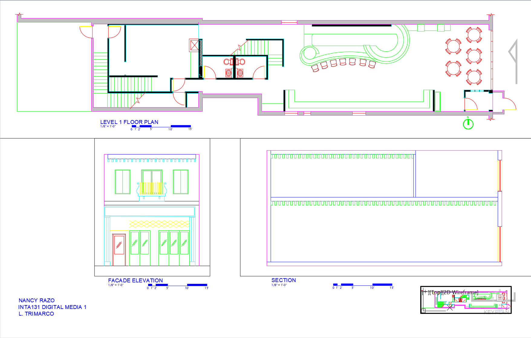
The final project began in AutoCAD drawing the first floor (Level 1) plan using hand-outs given in class. All Interior Walls are 5" in depth, Exterior Walls are 1'-0" in depth, Plumbing Walls 8" in depth and all Door Openings are a minimum of 3'-0" wide. By referencing standard layer listings, I created new layers specific to the floor plan: A-WALL-EXTERIOR, A-WALL-EXTERIOR-PATT, A-WALL-EXTERIOR-GLASS, A-COLS, A-GLAZ (Window Glass), A-GLAZ-SILL (Window-Sills), A-FURN, A-PLUMB-FIXT, A-FLOR-STRS (Stairs), etc. Additionally, a title, Architectural Scale of 1/8"=1'-0", North Arrow, and my name were added to the drawing upon completion.
Facade Elevation (Week 11-12)
I began drawing the Final Project Facade Elevation in AutoCAD. Working within the same AutoCAD drawing as the First Floor (Level 1) plan, I created new layers specific to the Facade Elevation: I-ELEV-1, I-ELEV-1-HIDDEN, I-ELEV-2, I-ELEV-3, I-ELEV-4, I-ELEV-5, and I-ELEV-6. These would serve to locate exterior wall features such as doors and windows. As before, labels were properly added to identify the drawing, scale, and direction.
North Section (Week 13)
I began drawing the Final Project North Section in AutoCAD. Again, I worked within the same AutoCAD drawing as the First Floor (Level 1) plan and Facade Elevation. Utilizing the same layer listings as the Facade Elevation, I created exterior walls, floor, and roof. Labels were properly added to identify the drawing, scale, and direction.
Final Project Deliverables (Week 14-15)
To its completion, this project consists of: (1) Setting up a presentation sheet in AutoCAD Paperspace, (2) Adding shadows to the floor plan, elevation, and section in Photoshop, (3) Adding people to my elevation and section in Photoshop, (4) Setting up a presentation sheet in InDesign, and (5) Placing the rendering Floor Plan, Elevation and Section to scale. Check out my final submission by clicking the button below!